A receiver can decode a signal whose received power is weaker than the noise in the same band. Deep-space telemetry, satellite navigation, and covert tactical links all depend on it. A spectrum analyzer at the antenna shows only noise, and still the decoder recovers the data without error. The noise floor appears to be a hard limit on what can be extracted; it is not. The paradox resolves once two quantities are kept apart: the signal-to-noise ratio over the occupied band, which has no lower bound, and the energy per bit relative to the noise density, which does. The relation between them is the substance of a weak-signal link budget, and it fixes how far beneath the noise floor a receiver can operate.
The receiver noise floor and sensitivity
The noise floor of any receiver begins with the thermal noise at its input. A resistor at temperature delivers a noise power spectral density dBm/Hz at room temperature. Raised by the front-end noise figure (NF), it becomes the input-referred noise density . The noise floor over a bandwidth is then [1]
with in hertz. A modulation and coding scheme (MCS) decodes once the SNR exceeds a minimum value , so the sensitivity of that MCS is
Note that nothing forces to be positive. A robust MCS can require a negative SNR in decibels, and then lies below the noise floor: the receiver recovers a signal weaker than the noise sharing its band. The remainder of the article examines how far can be reduced, by what mechanisms, and against what limit.
Signal-to-noise ratio, energy per bit, and spectral efficiency
At the analog front end the relevant quantity is the received SNR over the occupied bandwidth, whereas the decoder operates on the energy per information bit. The two are related by a factorization of the SNR:
the product of a fundamental quantity, the energy per bit , and an architectural one, the spectral efficiency . Here is the received signal power, the energy per information bit, the detection figure of merit [2], and the bits per second carried in each hertz of occupied bandwidth .
For a fixed noise floor, sensitivity improves by lowering , which is possible in two ways:
- Reduce the bit rate : the required signal power drops by per decade of rate, the fall in a byproduct (widening instead would lift the floor by the same amount and cancel). Holding a low rate in a fixed channel, occupying more bandwidth than the information needs, is exactly spreading.
- Lower the required : by the coding gain of FEC toward the dB wall, or by multi-antenna processing.
Spreading: processing gain at fixed bandwidth
Reducing the bit rate is the first lever, and spreading is how a low rate occupies a fixed channel. In an occupied bandwidth , an information rate needs an information bandwidth of only , far narrower than ; direct-sequence spreading widens each symbol back to with a chip sequence [3], at a spreading factor equal to the ratio,
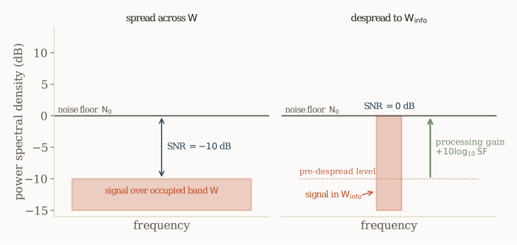
Spread across , the signal occupies times more bandwidth than the information requires, so its occupied-band SNR is a factor below its value in the information band at fixed . Despreading correlates against the known chip sequence, summing the chips coherently while the uncorrelated noise adds incoherently, and the signal collapses back to with its SNR lifted by ,
Take : a signal at dB in the occupied band () despreads over ten chips to dB in the information band, level with the noise and decodable (Fig. 1). Because the low rate is what set the narrow information band, the of processing gain and the rate reduction are the same number: spreading is the mechanism, the reduced rate is the source of the sensitivity gain, and is unchanged. The processing gain is an integration gain. In the time domain, a lower rate lengthens the time per bit , so the receiver collects the energy the decoder requires from a proportionally lower received power, integrated over the longer symbol. Despreading realizes the same integration in the chip domain: it coherently sums the chips of each symbol, and a lower rate integrates over more of them.
The mechanism is not confined to deep-space links; LoRa applies it directly. Its chirp spread spectrum holds a fixed channel, typically kHz, and selects a spreading factor from SF7 to SF12, each step doubling the symbol length and adding roughly dB. Its sensitivity runs from about dBm at SF7 to dBm at SF12 in the same channel. GPS carries it further: a Mchip/s coarse/acquisition code carrying a bit/s message has a processing gain of dB, so the signal arrives roughly dB below the thermal noise and is recovered by despreading. Both trade rate for range within a fixed band.
Processing gain places the signal at a chosen negative occupied-band SNR, and with it a sensitivity below the noise floor. It leaves unchanged, which the next section shows is the one quantity that is bounded.
Coding gain and the energy-per-bit wall
The Shannon capacity of an additive white Gaussian noise channel of bandwidth , power , and noise density is [4]
Reliable communication needs . Dividing by recasts this in spectral efficiency:
Substituting gives the energy-per-bit bound,
the least energy per bit any modulation and code can spend at spectral efficiency , the curve of Fig. 2. It rises with ( needs dB, needs dB) and is smallest as . Expanding ,
This is the wall: no bandwidth, coding, or spreading beats dB, approached only as , that is with infinite bandwidth [5].
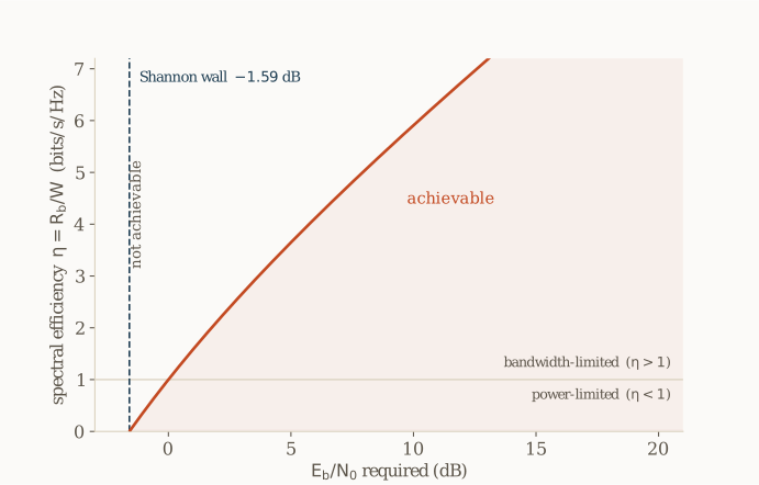
Lowering walks the operating point down the curve toward the wall, which infinite bandwidth reaches and nothing passes. Coding gain is what walks a finite-bandwidth system toward it, and how close it gets, against what it costs, is the next section.
Coding gain versus processing gain
Two mechanisms expand the bandwidth, serving different purposes. Coding gain, from forward error correction (FEC), lowers the required toward the dB wall, the only lever that moves the fundamental requirement. Processing gain, from spreading, lowers the occupied-band SNR at fixed : it provides robustness rather than range, since a spreading code is only a repetition code and adds no coding gain in a Gaussian channel. In fading it earns more, its independently faded copies giving diversity, a steepening of the error-rate curve that coding alone does not provide [6].
The same reads as robustness or as range depending on what is held fixed. Hold the information rate and widen the band: the occupied-band SNR falls, does not, and the gain is robustness with no added range. Hold the band and take the expansion from a lower rate, as with GPS and LoRa: each bit carries more energy, rises, and the same factor is range.
A real link spends its bandwidth budget on both,
giving FEC as much as the decoder complexity allows, since only FEC reduces the required , and the rest to spreading for the robustness FEC cannot provide: interference rejection, multipath resolution, multiple access, and low probability of intercept. Satellite navigation is the canonical balance, heavy spreading for jam resistance and multiple access alongside FEC for the coding gain that approaches the wall. The split is an implementation-complexity trade-off, not a fundamental one.
Designing a long-range link
These results combine into a design procedure. Consider a telemetry link that must close over a long range within a fixed channel of kHz, with noise figure dB, so the input noise density is dBm/Hz. Take BPSK with a rate- low-density parity-check (LDPC) code, decoding at dB.
Range follows from sensitivity, and sensitivity from a low rate. At the required , the minimum received power is the energy per bit the decoder needs, spent at the bit rate:
A lower rate lengthens the time per bit , so the receiver collects the energy the decoder requires from a proportionally lower received power, integrated over the longer symbol. This is the mechanism behind the whole article. Taking of this, writing the noise density as dBm/Hz, and adding an implementation loss for the gap from the ideal (carrier and timing synchronization error, phase noise, channel-estimation error, filter and pulse-shaping mismatch, and quantization, typically to dB), the sensitivity, with in bit/s, is
Every term is a design lever, and bandwidth is not among them. The only ways to improve sensitivity are a lower noise figure, a lower bit rate ( per decade, unbounded), a lower required from coding gain toward the wall, an array gain of from multi-antenna processing (maximum-ratio combining of antennas sums the branch SNRs), or less implementation loss. In summary:
| Lever | Sensitivity term it moves | Bandwidth cost | Ceiling |
|---|---|---|---|
| Lower noise figure | NF | none | hardware |
| Reduce bit rate | none (spread to fill W) | unbounded | |
| Coding gain (FEC) | expands W | −1.59 dB wall | |
| Multi-antenna processing | array gain | none | , plus diversity |
| Spreading at fixed Rb | in-band SNR only | expands W | 0 dB (robustness only) |
Consider two rates in the same kHz channel with . Filling the channel with data at kbit/s gives dBm. Dropping the rate a hundredfold, to kbit/s, gives dBm, dB better, purely through the of the rate. The low-rate signal now occupies an information bandwidth of only kHz, so filling the kHz channel spreads it by ; the dB of sensitivity and the dB of processing gain are the same number.
Suppose the geometry delivers a received power dBm at the design range. The received energy per bit is
so the low-rate link closes with dB of margin, while the high-rate one, at dB, falls far short of the requirement. Over the kHz channel the noise floor is dBm, so the received signal at dBm sits dB beneath it: a spectrum analyzer shows only noise. Despreading recovers the dB of processing gain, lifting the information-band SNR from dB to dB, and the rate- code supplies the last dB (its two coded symbols per bit), for dB. An occupied-band SNR of dB and an energy per bit of dB coexist without contradiction; the analyzer reading is an artifact of the spread, and the decoder responds only to .
The reverse case is instructive. Had the rate stayed fixed and the bandwidth been expanded by spreading, rather than the rate lowered inside a fixed band, sensitivity would not have moved at all: at fixed the term is fixed, and spreading then provides only robustness. The two cases differ only in whether the bandwidth or the rate is held fixed, and the sensitivity depends entirely on the rate. Charging the spreading bandwidth to the link budget or reading the buried SNR as a shortfall is the most common error in weak-signal design.
The budget closes, but a digital receiver adds one more noise floor, set by the analog-to-digital converter (ADC) and the gain ahead of it. With the automatic gain control (AGC) applying a gain and the ADC full scale taken as dBm, the thermal noise referred to the converter is
so the AGC gain lifts the thermal floor to a usable level inside the converter’s range. Quantization is the second floor. With complex I/Q sampling the Nyquist rate equals the channel bandwidth, so no oversampling gain spreads the quantization noise, and the signal-to-quantization-noise ratio (SQNR) of an -bit converter is
bandwidth-independent, at dBFS for bits and dBFS for . The two add in power to give the digital noise floor the decoder sees,
Whether collapses onto depends on the margin between the two floors, which the ADC resolution and the AGC gain set together. A wide margin leaves the receiver thermal-limited. For a representative front end, dB and dB:
| BW (MHz) | Bits | Thermal (dBFS) | Quant. (dBFS) | Margin (dB) | Combined (dBFS) |
|---|---|---|---|---|---|
| 2.5 | 12 | −67.0 | −74.0 | 7.0 | −66.2 |
| 2.5 | 16 | −67.0 | −98.1 | 31.1 | −67.0 |
| 5 | 12 | −64.0 | −74.0 | 10.0 | −63.6 |
| 5 | 16 | −64.0 | −98.1 | 34.1 | −64.0 |
| 10 | 12 | −61.0 | −74.0 | 13.0 | −60.8 |
| 10 | 16 | −61.0 | −98.1 | 37.1 | −61.0 |
At bits the quantization floor sits dB or more below thermal, the combined floor equals the thermal one, and the receiver is thermal-limited at every bandwidth. At bits the margin narrows to dB at MHz, where quantization lifts the floor by nearly a decibel, a direct loss of sensitivity that eases at wider bandwidth only because the thermal floor itself rises. The design goal is simple: enough AGC gain to lift the thermal floor clear of quantization, and enough resolution to keep it there. The digital floor then falls back onto the analog one the rest of the article assumed [1].
Digitization is only half of realizing the processing gain; the other half is synchronization, since the receiver must acquire and track the code and carrier at the operating SNR, and any residual misalignment is the implementation loss of the sensitivity equation, paid straight onto the required .
The two things that never move
A weak-signal receiver decodes beneath the noise floor because the occupied-band SNR has no lower bound: spreading drives it as negative as allows, and despreading recovers the loss coherently. Two quantities do not move. The noise floor over the true detection bandwidth is set by temperature, bandwidth, and noise figure. The energy-per-bit wall sits at dB, the limit of the Shannon bound, and no bandwidth expansion crosses it. Operating below the noise floor is a statement about power and SNR, always achievable; operating below dB of energy per bit is a statement about information, never achievable. Keeping the two apart, a low rate and coding for sensitivity, spreading for robustness, is the discipline of weak-signal design. The same accounting decides whether a waveform can be hidden under the noise while still being read, where a later post on low-probability-of-intercept design will begin.
References
[1] B. Razavi, RF Microelectronics, 2nd ed. Prentice Hall, 2011.
[2] J. G. Proakis and M. Salehi, Digital Communications, 5th ed. McGraw-Hill, 2008.
[3] R. L. Pickholtz, D. L. Schilling, and L. B. Milstein, “Theory of spread-spectrum communications: a tutorial,” IEEE Transactions on Communications, vol. 30, no. 5, pp. 855–884, 1982.
[4] C. E. Shannon, “A mathematical theory of communication,” The Bell System Technical Journal, vol. 27, no. 3, pp. 379–423, 1948.
[5] S. Verdú, “Spectral efficiency in the wideband regime,” IEEE Transactions on Information Theory, vol. 48, no. 6, pp. 1319–1343, 2002.
[6] D. Tse and P. Viswanath, Fundamentals of Wireless Communication. Cambridge University Press, 2005.