Long-range terrestrial links, from drone relays to tactical radios, are limited by the shape of the Earth as much as by their power budget. The received signal weakens with distance, but the ground also curves away, and past a certain range the two terminals can no longer see each other at all. That range, the horizon, is often quoted as the hard limit on a beyond visual line of sight (BVLoS) link. It is not. Radio waves bend past the geometric edge, diffract into the shadow behind it, and on some days duct for hundreds of kilometers. This post works through the geometry and the propagation that set real BVLoS range, and closes with a drone budget tied to the receiver sensitivity of the previous post.
The radio horizon is not the range limit
The geometric horizon follows from a tangent line to a sphere. For an antenna at height above a smooth Earth of radius , the tangent grazing distance is . With km and in meters, this is
Radio waves do not travel in straight lines through the atmosphere. The refractive index falls with altitude, so a ray bends gently downward and follows the curvature a little way past the geometric tangent. The standard correction replaces with an effective radius , where for a median atmosphere [1]. The radio horizon is then about 15% longer,
and for a link between two terminals it is the sum of their horizons, . Figure 1 shows the two grazing rays from a single elevated terminal. The radio ray clears the flatter 4/3-Earth surface and reaches further than the geometric one.
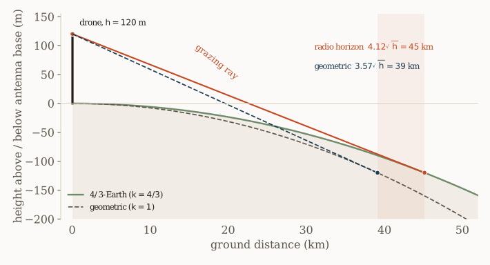
One point deserves emphasis: even the radio horizon is only where the direct ray grazes, not where the signal ends. Diffraction carries energy into the region beyond, so the radio horizon bounds line of sight, not communication.
The propagation regimes
Within radio line of sight the signal still weakens with distance, and it does so in stages that a single free-space figure misses. Two distances mark the transitions. Take the running example of this post: a 120 m drone linking a 2 m ground terminal at 900 MHz. The two terminals’ horizons add, the drone reaching 45 km on its own and the ground station a further 6 km, for a link radio horizon of about 51 km. In practice this two-terminal figure sets the range, not either terminal alone. Nearer in, the breakpoint falls at about 2.9 km, where the ground reflection begins to cancel the direct ray and the loss steepens. The link radio horizon at 51 km is where the direct ray is finally blocked and only diffraction reaches into the shadow. The two are an order of magnitude apart, , and they play very different roles. A link passes through three regimes as range grows, measured against free space as the reference:
| Regime | Distance | What happens | Falloff |
|---|---|---|---|
| Free space | reference | direct ray only, first Fresnel zone clear | |
| Two-ray, below breakpoint | direct and reflected rays oscillate around free space, with deep nulls | ||
| Two-ray, above breakpoint | direct and reflected rays nearly cancel | ||
| Diffraction | Earth blocks the direct ray, field bends into the shadow | steep |
where is the breakpoint and the radio horizon. The first three regimes are line of sight; only the last lies beyond it. Later sections put numbers on them: the two-ray loss and its breakpoint, then the diffraction loss past the horizon.
The term “beyond line of sight” needs care against this map. Visual line of sight, the operator’s eyesight, is only a kilometer or two for a small drone, far shorter than the radio horizon. A BVLoS drone link is beyond that visual limit but is kept within the radio horizon by flying high, so the radio operates in the two-ray regime, not the diffraction regime. Operating beyond the radio horizon, in the diffraction region, carries tens of decibels of excess loss and is avoided in a well-designed link.
Antenna height dominates
Because range grows as , height is the strongest lever on a terrestrial link. Doubling the range requires four times the height. Raising one terminal from a 2 m tripod to a 120 m drone extends its horizon from about 6 km to 45 km, nearly an eightfold gain from geometry alone. Figure 2 traces the square-root law.
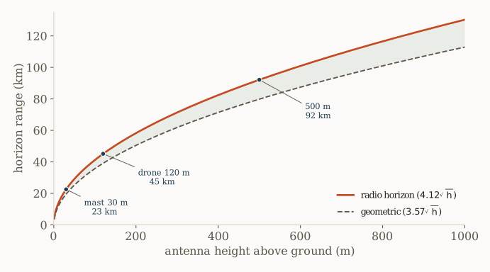
Height is not simply another term in the budget. Transmit power adds decibels of margin to a link that already closes, but no amount of power creates line of sight where the Earth blocks it. Past the radio horizon the direct ray is gone, and the signal that remains has propagated by diffraction or tropospheric scatter, with tens of decibels of excess loss. Height changes the propagation regime; power only scales it. This is why a modest transmitter on a high platform outperforms a strong one on the ground.
Path loss beyond free space
The two line-of-sight regimes differ only in how fast the loss grows with distance. Free-space loss follows the inverse-square law [2],
which rises 20 dB per decade of distance. Over real ground a second ray reaches the receiver, the reflection off the surface. It arrives with a phase set by the extra path length, and at long range, where the grazing angle is small, the reflection coefficient approaches . Direct and reflected rays then nearly cancel, and the received power falls as rather than . The plane-earth loss is [3]
with and the heights in meters. It rises 40 dB per decade and does not depend on frequency. The crossover between the two regimes is the breakpoint,
where the first Fresnel zone first touches the ground. That zone is the ellipsoid around the direct ray within which a secondary path is less than half a wavelength longer than the direct one; its radius at a point splitting the path into lengths and is , widest at midpath, and an obstruction inside it interferes with the signal. Below the breakpoint the two rays interfere and the loss oscillates around the free-space curve. Above it the law takes over. Figure 3 shows both.
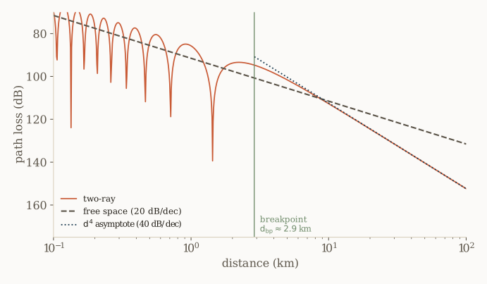
For long range with modest antenna heights the breakpoint sits at a few kilometers, so a link of tens of kilometers is deep in the regime. The free-space number quoted for such a link understates the loss by 20 dB per decade past the breakpoint. That is the first correction a BVLoS budget needs.
Diffraction and Fresnel clearance
Beyond the radio horizon the direct ray is blocked, yet a link can still close. Radio waves diffract around the Earth’s curvature and over terrain, filling the geometric shadow with a field that decays smoothly rather than vanishing. The loss relative to free space is governed by the Fresnel-Kirchhoff diffraction parameter,
where is the height of the obstruction above the direct ray, negative when the ray clears it, and are the distances to the obstruction. A single ridge is modeled as a knife edge, whose loss depends only on [4]. Figure 4 plots it.
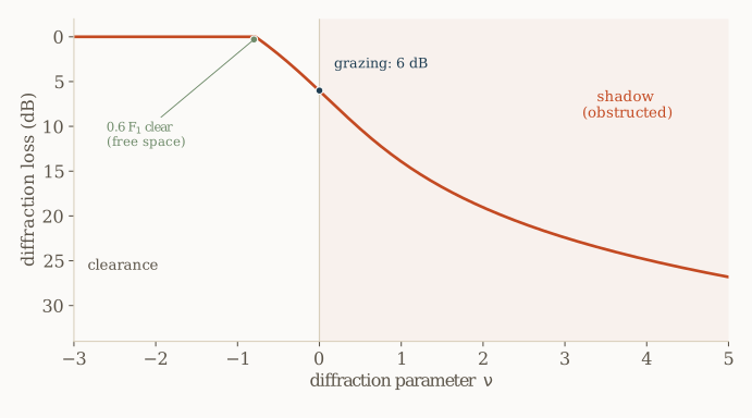
Two thresholds matter in practice. Full free-space behavior needs the ray to clear an obstruction by about 0.6 of the first Fresnel zone radius; at grazing, where the ray just touches the obstruction, a knife edge already costs 6 dB. This clearance is a line-of-sight criterion and applies well within the radio horizon. The obstruction may be a hilltop or the Earth’s own bulge rising into the zone as the path lengthens. Clearance shrinks with range until the bulge grazes the ray at the radio horizon; beyond it the direct ray is blocked, and the smooth-sphere diffraction loss, heavier than a single knife edge, adds to the free-space path loss. The principle is the same throughout: the shadow is illuminated at a cost that the geometry predicts.
The atmosphere and the 4/3 fiction
The factor rests on a standard refractivity gradient of about N-units per kilometer. That gradient is a long-term median, and the real atmosphere departs from it hour to hour. When the gradient is weaker, the radio horizon shortens (sub-refraction). When it is stronger, it extends, and beyond a critical gradient the atmosphere traps the wave against the surface entirely. This is ducting, a super-refractive layer that can carry a signal hundreds of kilometers past its nominal horizon, common over water and in coastal and evening conditions [5]. Figure 5 shows the horizon sliding with .
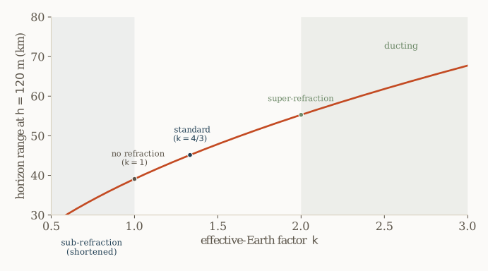
For a link designed to a fixed range this variability cuts both ways. Ducting is an opportunity for occasional long reach and a hazard for co-channel interference from distant transmitters. Sub- refraction is a fade mechanism that a static budget does not capture. The horizon is a planning figure, not a guarantee for any given hour.
A worked BVLoS budget
The pieces combine into a range budget for the running example. The drone at 120 m carries a 2 dBi antenna and 30 dBm (1 W) of transmit power; the ground station at 2 m has a 10 dBi directional antenna. The target range is 40 km, inside the two-terminal radio horizon of km and well past the 2.9 km breakpoint, so by the map above the link is line of sight, deep in the two-ray regime.
The path loss uses the regime. At 40 km the free-space figure is 123.6 dB, and the two-ray loss is
an excess of 12.9 dB over free space. The received power is the transmitted power plus the two antenna gains minus the path loss,
Whether the link closes is decided by the receiver sensitivity. From the previous post, sensitivity is the noise density, the rate, the required energy per bit, and the implementation loss, with no dependence on bandwidth [6]:
At a data rate Mbit/s, noise figure 5 dB, required of 8 dB, and 2 dB of implementation loss,
The link closes with a margin of dB. The full budget:
| Term | Value |
|---|---|
| Transmit power, | 30 dBm |
| Drone antenna gain | 2 dBi |
| Ground antenna gain | 10 dBi |
| Free-space loss at 40 km | −123.6 dB |
| Two-ray () excess | −12.9 dB |
| Received power, | −94.5 dBm |
| Receiver sensitivity, | −99.0 dBm |
| Margin | 4.5 dB |
The design levers are visible in the budget. Raising the drone lifts the horizon, and in the two-ray regime it also lowers the path loss by 20 dB for every tenfold increase in height, on top of protecting the Fresnel clearance and buying margin against sub-refraction. A lower data rate lowers the sensitivity directly, as the previous post showed. A higher gain antenna helps, at the cost of pointing. Transmit power is the weakest lever because it scales the margin without changing the geometry that sets whether a link is possible at all.
The height dependence makes this concrete. Fix the range at 40 km, along with the transmit power, gains, and rate, and vary only the drone height, holding the ground terminal at 2 m. Within line of sight the excess over free space is the two-ray figure; beyond the radio horizon it is the spherical-earth diffraction loss of ITU-R P.526 [4], computed here for horizontal polarization over average ground, which deepens quickly into the shadow.
| Drone height (ground 2 m) | Radio horizon | 40 km path | Excess over free space | Margin |
|---|---|---|---|---|
| 120 m | 51 km | within radio horizon | +12.9 dB (two-ray) | +4.5 dB |
| 40 m | 32 km | 8 km beyond radio horizon | +35.6 dB (diffraction) | −18.2 dB |
| 15 m | 22 km | 18 km beyond radio horizon | +46.1 dB (diffraction) | −28.7 dB |
At 120 m the radio horizon reaches 51 km, so the path is comfortably within line of sight and the link closes with 4.5 dB of margin. Drop the drone to 40 m and the radio horizon falls to 32 km, putting the path 8 km into the diffraction shadow, where P.526 adds 36 dB and the link fails by 18 dB. At 15 m the shadow is 18 km deep, the diffraction loss reaches 46 dB, and only far more height, gain, or a far lower rate could recover it. Height does not merely trim the budget: it decides whether the link is line of sight or diffraction-limited, a difference of tens of decibels.
What the radio horizon formula hides
The radio horizon is a useful first number and a poor last one. It assumes a fixed atmosphere when swings from sub-refraction to ducting. It assumes a smooth sphere when real terrain both blocks the signal and diffracts it past the geometric edge. It treats the radio horizon as a boundary when the field beyond it is a predictable diffraction loss, not zero. And it says nothing about path loss, which past the breakpoint follows the law rather than the free-space figure most budgets quote.
Real BVLoS range follows from the full budget. That budget weighs the path loss and any diffraction loss beyond the radio horizon against the receiver sensitivity and a fade margin. Two transitions along the way are easily mistaken for the end of the link. At the breakpoint free space gives way to the law; at the radio horizon line of sight gives way to diffraction. The link ends at neither. It ends where the accumulated loss finally exceeds the receiver sensitivity.
References
[1] J. D. Parsons, The Mobile Radio Propagation Channel, 2nd ed. Wiley, 2000.
[2] ITU-R Recommendation P.525, “Calculation of free-space attenuation,” International Telecommunication Union, Geneva, 2019.
[3] T. S. Rappaport, Wireless Communications: Principles and Practice, 2nd ed. Prentice Hall, 2002.
[4] ITU-R Recommendation P.526, “Propagation by diffraction,” International Telecommunication Union, Geneva, 2019.
[5] ITU-R Recommendation P.453, “The radio refractive index: its formula and refractivity data,” International Telecommunication Union, Geneva, 2019.
[6] B. Razavi, RF Microelectronics, 2nd ed. Prentice Hall, 2011.